Dial Indicator Types
THE DIAL INDICATOR TYPES
There are two main dial indicator types:
- Lever Dial Test Indicator
- Plunger Dial Indicator


Both dial indicator types have similar features while functioning differently. Understanding the differences in function and the variations in the characteristics of each will help you determine which is the correct instrument for your application.
In this article, we go over each indicator type in detail. We discuss functions, features, and their typical applications.
Let’s start with Plunger Dial Indicators.
PLUNGER DIAL INDICATOR
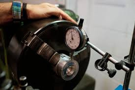
Plunger Dial Indicators (often referred to simply as Dial Indicators) use a plunger that moves in a straight line to magnify and convert the force applied to the contact point (at the bottom of the plunger) into a measurement.
FEATURES AND USES
Generally larger and heavier than test lever dial indicators, plunger dial indicators are most suited to repetitive, comparative measurements. An example of this is that once set up on a stand or height gauge, plunger dial indicators are great at quickly checking the measurements of a batch of components to ensure they are within the required tolerance.
Plunger dial indicators are also often used in machine setups to monitor changes in the alignment of machine parts and components. The plunger dial indicator needs to be positioned at an angle of 90° to function accurately. Using an indicator stand is the best way to do this, with the plunger slotting into a mounting.
Plunger dial indicators are also better suited for measuring larger movements than lever dial test indicators, due to cosine error, explained below.
LEVER DIAL TEST INDICATOR
Lever Dial Test indicators are also known as a lever-type indicator, a DTI or simply a dial test indicator. The bottom of the body houses a pivot with a probe (the lever), its distinguishing feature when visually comparing the two dial indicator types.
FEATURES AND USES
Lever dial test indicators are more suited for measuring small movements than their larger cousins, for example checking linear and geometric features on a component. Lever indicators are commonly used to measure the amount of material removed during grinding or milling.
The lower spring force and angled movement of the lever responds dimensional changes. Generally speaking lever indicators are used to monitor small changes during machining or to measure geometric features such as ovality or runout.


PROBE/CONTACT POINT LENGTH AND DIAMETER
The length and diameter of the contact point needed will depend on the application. A long thin probe may be required to reach into a narrow recess for example. It is possible to purchase probes/contact points of different sizes for specific uses.
However, it is important to use the brands (or brand recommended) products and to calibrate the instrument ready for the new application. Using a length of probe, that the test indicator is not designed to accommodate can cause incorrect magnification of the force, resulting in incorrect measurements/readings.
Considering this, buying a lever dial test indicator with a specifically suited probe/contact point for each application is possibly the best bet. The shape, size, and material of the contact point is a consideration discussed later in the article, and is relevant for both dial indicator types.
COSINE ERROR
A little basic trigonometry (if there’s such a thing!) is required to explain and fix the most common error when using a test lever dial indicator.
WHAT IS COSINE ERROR?
Before we get into any formulas, let’s explain what causes the error.
The test lever dial indicator provides the most accurate measurements when its probe is positioned parallel to the surface of the item being measured, as shown here.
If it isn’t possible to position the dial indicator parallel to the measuring object then the probe can be angled while the contact point achieves the required parallel position, as shown below.

When the contact point of the measuring probe is not parallel to the measuring surface, it will result in inaccurate measurements, an error known as a cosine error.

HOW TO AVOID COSINE ERROR
To avoid cosine errors the test lever indicator must be set on a stand and positioned at a 0° angle, ensuring it is parallel or radial to the measuring surface. However, depending on the application, environmental factors such as material position and available space mean this is not always possible. Cosine errors will inevitably occur in some situations, and it is important to know how to adjust for them.
HOW TO FIX COSINE ERROR
This is where the math comes in. The triangle formed between the contact point/probe and the measuring surface can calculate the amount of error present in the measurement.

We need to know the unknown angle of the right-angled triangle, which is calculated like this:
- We know the length of the hypotenuse – it is the length of the contact point.
- We (should) know the length of the adjacent side of the triangle – it is the length of (or part of) the measuring surface.
- We then calculate adjacent/hypotenuse.
- We then grab our calculator and hit the ‘cos-1’ key!
Now we know the angle we use our calculator again to establish the adjustment we need to make to the measurement.
- Put the angle into your calculator and push the ‘cos’ key.
- Multiply the resulting number by the measurement reading, which will give you the correct measurement – simple!
Note: We’ve tried to offer a quick and easy to understand calculation explanation. For a full recap on sine, cosine, tangent, and calculating angles check out this great article.


